Phone Number: +86 158 1244 0593

Motor Wire Harness Assembly

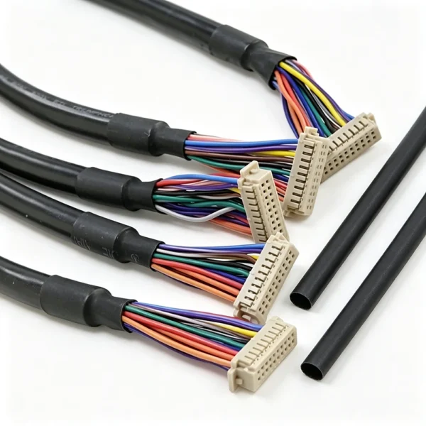
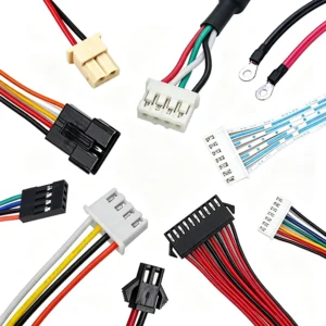
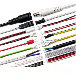
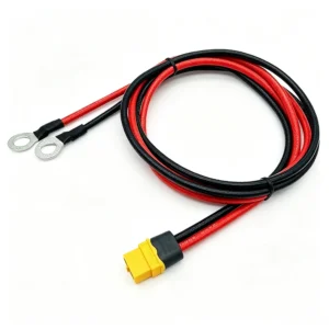
Motor Wire Harness Assembly connects motors with power sources, control boards, drivers, switches, or feedback circuits inside electrical and electronic equipment. Fengzhan provides configurable motor wiring with specified wire sizes, connectors, terminals, lengths, and circuit arrangements for different equipment designs. Assemblies can be developed from drawings, wiring diagrams, samples, or component specifications.

Connector Type
JST, Molex, Custom Connectors
Terminal
Crimp terminals or application-specific terminals
Circuit
Power, control, feedback or combined circuits
Protection
Heat shrink, sleeving, tubing or other options
Assembly Type
Single-branch or multi-branch configurations
Cable Length
100-2000mm or Customzied
Insulation
PVC, Silicone, PUR or others
MOQ
100 PCS

Motor Wiring for Power, Control and Equipment Integration

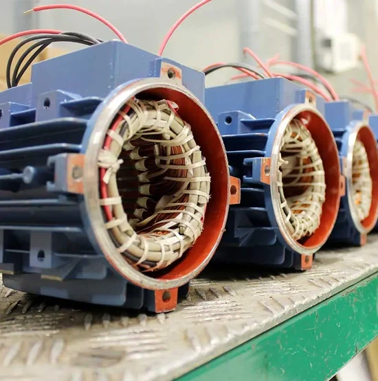
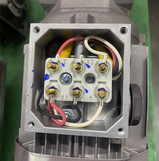
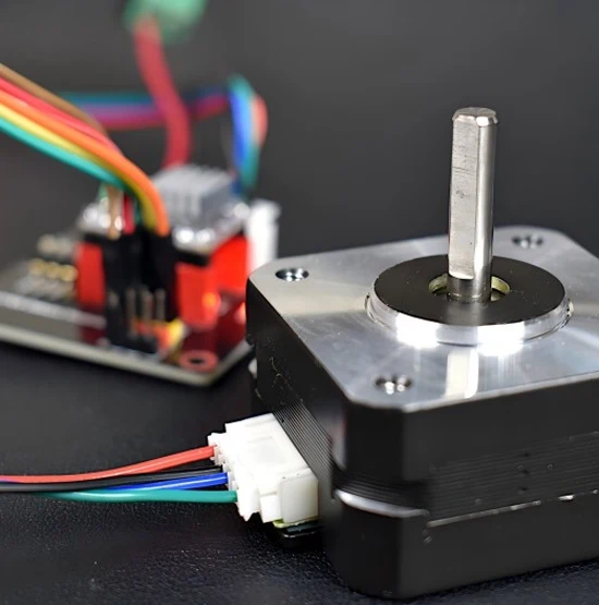
Motor wire harness assemblies are designed to connect motors with power supplies, control boards, drivers, switches, or other electrical components inside equipment. Depending on the motor and application, the assembly may carry power, control signals, feedback connections, or a combination of different circuits. Fengzhan can process and assemble wires with the required terminals, connectors, protective materials, and routing structure.

Wire length, conductor size, connector configuration, and termination method can be adapted to the equipment design. Customers can provide motor specifications, wiring diagrams, connector part numbers, samples, or existing assemblies for evaluation. The resulting harness can help simplify internal wiring and provide an organized connection between the motor and the surrounding electrical system.

Where This Motor Harness Is Used

Industrial Machinery

Industrial Machinery

Pumps, Fans & Blowers

Pumps, Fans & Blowers

Motorized Appliances

Motorized Appliances

Automation

Automation

Technical Features for Motor Wiring

Motor wiring is designed around both electrical requirements and the physical structure of the equipment. Conductor selection, termination, connector placement, and cable routing can be coordinated during development. Where the assembly passes through limited spaces or areas involving movement, its length, branch positions, and protective materials can be considered as part of the overall configuration.

01 — Application-Specific Conductor Selection

Wire size can be selected according to the intended power, control, or feedback circuit requirements.

02 — Multiple Connector Interfaces

JST, Molex, or other specified connectors can be incorporated when they match the motor, controller, or equipment interface.

03 — Organized Circuit Routing

Individual conductors and branches can be arranged to follow the internal routing path of the equipment.

04 — Flexible Branch Structures

Single-branch or multi-branch layouts can be developed depending on the number and location of connected components.

05 — Terminal and Connector Orientation

Termination and connector positioning can be considered where installation space or mating direction affects the assembly design.

06 — Protection for Internal Routing

Heat-shrink tubing, sleeving, or other protective materials can be incorporated where required by the mechanical structure or installation environment.

Common Motor Wiring Functions

Motor wiring can serve more than a basic power connection. Depending on the equipment architecture, one assembly may carry motor power, connect control inputs, transmit feedback signals, or combine several circuits. These functions can be organized into a practical wiring structure that matches the motor, controller, and installation requirements.

Motor Power Connection

Provides the electrical path between the motor and its designated power source, with conductor selection based on the required circuit and operating conditions.

Motor Feedback Connection

Provides dedicated conductors for feedback devices such as encoders or position and speed sensing circuits where required by the motor system.

Combined Power & Control

Power, control, and feedback conductors can be organized within one assembly when multiple motor-related connections need to share a common wiring structure.

Motor Control Connection

Links the motor with a controller, driver, relay, or PCB used to manage starting, stopping, speed, or other operating functions.

Power Wiring for Motor-Driven Equipment

Motor connections are often part of a larger electrical power system within the equipment. If your project requires wiring that extends beyond the motor itself and connects multiple power-consuming components, our Connector Cable Assemblies may be a better fit for broader equipment power distribution.


Explore Connector Cable Assemblies →

Common Motor Wiring Configurations

Motor connections can take different forms depending on the equipment layout and electrical architecture. A harness may run directly to a power source, interface with a PCB or motor driver, or combine several circuits in one assembly. Branching, connector placement, conductor arrangement, and cable length can be adapted to the installation space.

Motor-to-PCB Connection

The assembly provides a defined interface between the motor and a PCB or control board through the required connector or terminal arrangement.

Motor-to-Driver Connection

Wiring connects the motor with its driver or controller according to the required circuit layout and mating interface.

Multi-Circuit Motor Harness

Power, control, and feedback conductors can be combined into one organized assembly when several motor-related circuits are required.

Motor-to-Power Connection

A dedicated cable connects the motor to its power source using the specified wire size and termination method.

Customized Motor Wiring Configured Around Your Equipment

Motor wiring can be developed around the motor interface, electrical requirements, and available installation space. Custom options may include conductor size, cable length, connector type, terminal selection, circuit arrangement, branch structure, and protective materials. The assembly can be configured for power, control, feedback, or combined connections. Customers can provide motor part numbers, drawings, wiring diagrams, samples, BOMs, or existing assemblies for engineering review and production planning.

Cable Structure Customization

- Cable length
- Wire quantity
- Wire gauge
- Cable color
- Pin configuration

Connector Customization

- Connector selection
- Terminal type
- Housing selection
- Pin arrangement
- Connector replacement

Protection Customization

- Heat shrink protection
- Braided sleeving
- Shielding layer
- Waterproof sealing
- Special insulation materials

Manufacturing Requirements

- OEM Design
- Prototype development
- Low-volume production
- High-volume manufacturing
- Customized packaging

Quality Control from Wire Processing to Final Testing

Motor wiring requires accurate conductor preparation and correct connections between the motor and associated electrical components. During production, wire dimensions, stripping, terminal crimping, and connector assembly are checked against the specified requirements. Finished assemblies can undergo continuity testing to identify open or incorrect circuits. Final inspection also verifies cable length, connector condition, terminal placement, circuit identification, protective materials, and overall workmanship before shipment.

1. Incoming material inspection

All incoming wires, connectors, terminals, and components are inspected to verify specifications, material quality, and compliance before entering the production process.

2. Wire cutting inspection

Wire cutting processes are carefully monitored to ensure accurate length, stripping dimensions, and consistent preparation for reliable assembly performance.

3. Crimping quality inspection

Crimping operations are inspected to ensure proper terminal connection, pull strength, and stable electrical performance according to production requirements.

4. Connector assembly inspection

Connector installation is checked to confirm correct pin positions, secure connections, and proper assembly quality for dependable cable performance.

5. Electrical continuity testing

Each cable assembly undergoes electrical testing to verify continuity, wiring accuracy, and reliable signal or power transmission before shipment.

6. Final appearance inspection

Finished products are visually inspected for appearance, labeling, protection, and overall assembly quality to ensure they meet customer specifications.

FAQ

FAQ 1
What information is needed to develop motor wiring?

A motor part number, wiring diagram, connector information, wire requirements, cable length, or existing sample can help define the required configuration. If some specifications are unavailable, customers can provide available drawings, photographs, or component samples for engineering review.


FAQ 2
Can one assembly carry both motor power and control circuits?

Yes. When permitted by the equipment design, power, control, and feedback conductors can be combined within one organized assembly. The circuit arrangement, wire specifications, connector interfaces, and termination points should be defined according to the motor and controller requirements.


FAQ 3
How do you determine the correct connector for a motor?

The connector should match the motor-side interface and the mating component while meeting the required circuit arrangement and installation conditions. A connector part number, sample, drawing, or photograph can help identify the appropriate interface before production.


FAQ 4
What should be considered when routing wiring around a motor?

The routing path should account for the distance between connection points, available installation space, nearby components, and any expected movement. Cable length, branch locations, protection, and connector orientation can be considered during the design review to achieve a practical installation.


FAQ 5
Can an existing motor cable be used as a reference for a new assembly?

Yes. An existing cable can provide useful information about wire length, connector interfaces, terminal positions, circuit arrangement, and physical construction. Customers can send a sample or supporting photographs and drawings so the assembly requirements can be reviewed before prototype or production.

    Request a Quote


    Share your project details with our team and get a customized wire harness or cables solution. Don't have a complete drawing? Send us what you have.


    ✓


    Browse Files


    Click or drag and drop files here


    No file selected


    JPG, PNG, PDF, DOC, XLS or ZIP · Max 10 MB

    Your Trusted Partner for Wire Harness And Cable Assembly Solutions

    Contact Us >>